Looking Good Tips About Can DC Circuits Be In Parallel

How To Calculate Power In Dc Parallel Circuits
Understanding Parallel DC Circuits
1. What Does "Parallel" Actually Mean in Circuit Land?
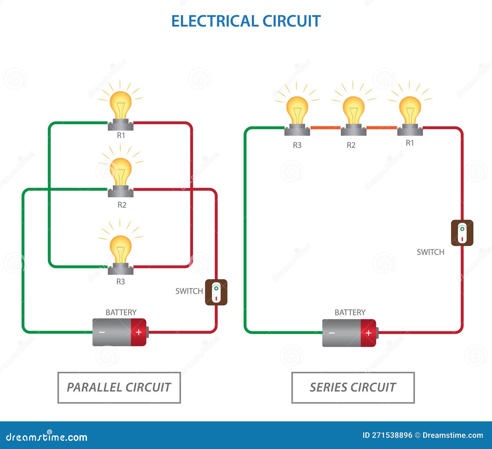
Alright, let's dive into the wonderful world of DC circuits! Now, when we say "parallel," we're talking about a specific way components, like resistors, are connected. Imagine a train track that splits into multiple paths, then merges back together. That's essentially what a parallel circuit is all about. Each component has its own separate pathway for current to flow from one side of the power source to the other. Think of it as multiple lanes on a highway; cars (electrons!) have choices!
In a parallel circuit, the voltage across each component is the same. This is super important to remember. If you have a 12V battery powering a parallel circuit, each resistor (or light bulb, or whatever you've got connected) will "see" 12V. This is different from a series circuit, where the voltage is divided among the components. So, it's like everyone gets the same slice of cake, instead of having to share one slice.
The total current in a parallel circuit is the sum of the currents flowing through each branch. In simpler terms, all the little currents going through each path add up to the total current coming from the battery. So, if you've got three branches pulling 1 amp each, the battery is supplying 3 amps. Makes sense, right?
Now, the resistance of a parallel circuit is a bit trickier to calculate, but it's always lower than the smallest resistance in the circuit. You can use a formula (the reciprocal formula) or online calculators to figure it out if you're doing any actual circuit design. Just remember, adding more resistors in parallel decreases the total resistance. It's counterintuitive but true! It's like adding more toll booths on a highway; the overall 'resistance' or congestion goes down because cars can spread out.
Can DC Circuits Be in Parallel? The Short Answer
2. Yes, Absolutely! In fact, it's Very Common
The core question: Can DC circuits be in parallel? The definitive answer is YES! DC circuits are frequently designed and used in parallel configurations. It's a fundamental concept in electrical engineering. Parallel circuits offer some unique advantages over series circuits, which makes them suitable for many applications.
One of the main reasons parallel circuits are so common is redundancy. If one branch of a parallel circuit fails (say, a light bulb burns out), the other branches continue to function normally. This is because each branch has its own independent path for current to flow. Contrast this with a series circuit, where if one component fails, the entire circuit breaks. Think of Christmas tree lights; the old kind that all went out when one bulb died those were wired in series (and were super annoying!). Newer sets use parallel wiring for this very reason.
Parallel circuits are also ideal for applications where you need to power multiple devices with the same voltage. Your house wiring is a prime example of a parallel circuit. All your outlets are wired in parallel, so each device plugged in receives the same 120V (in North America). Imagine if they were in series! The voltage would drop with each device, and your toaster oven would barely heat up by the time it got 'down the line' of outlets.
So, to reiterate, not only can DC circuits be in parallel, they often are, and for very good reasons!

Advantages of Parallel Circuits
3. Why Choose Parallel Over Series?
We've already touched on some of the benefits, but let's spell them out a little clearer. The most significant advantage of a parallel circuit is that each component operates independently. If one component fails, the others will continue to work without interruption. This reliability is crucial in many applications, like powering critical systems or devices that need to function continuously. Think hospital equipment or emergency lighting.
Another huge advantage is consistent voltage. Every component in a parallel circuit receives the full voltage of the power source. This ensures that each device operates at its designed specifications, providing optimal performance. In contrast, the voltage in a series circuit is divided among the components, which can lead to reduced performance if there are too many components.
The reduced total resistance offered by parallel circuits can be a big plus too. Lower resistance means higher current flow for the same voltage, which can be useful in certain applications, like powering motors or heaters that require a lot of current. Just be careful not to exceed the current rating of your power source or wires!
Finally, parallel circuits make troubleshooting easier. If a device isn't working, you can easily isolate the problem to that specific branch without affecting the operation of other devices in the circuit. It's like having individual switches for each appliance, allowing you to pinpoint the faulty one without shutting down the whole system.

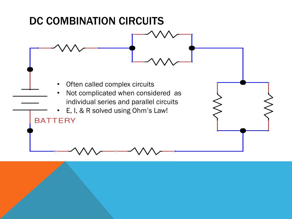
Series Parallel Circuit
Disadvantages of Parallel Circuits
4. It's Not Always Sunshine and Rainbows
While parallel circuits have many advantages, they also have some downsides. One potential issue is the higher current draw from the power source. Since each branch of the circuit draws its own current, the total current can be significantly higher than in a series circuit. This can overload the power source or require larger wires to handle the increased current.
Another disadvantage is that parallel circuits can be less efficient than series circuits in certain applications. If you have multiple devices that require different voltages, a series circuit might be a more efficient way to power them. In a parallel circuit, you would need to use voltage regulators to step down the voltage for each device, which can introduce losses.
Also, short circuits in a parallel circuit can be more problematic than in a series circuit. A short circuit in one branch can cause a large surge of current, which can trip a circuit breaker or damage the power source. In a series circuit, a short circuit might simply cause the entire circuit to stop working.
Finally, the complexity of calculating the total resistance in a parallel circuit can be a challenge, especially when dealing with many resistors or components with different resistance values. Although there are formulas and calculators to help, it can still be more involved than calculating the total resistance in a series circuit.

Practical Applications of Parallel DC Circuits
5. Where Do You Actually See These Things?
Parallel DC circuits are all around us, powering a wide range of devices and systems. We've already mentioned house wiring, where all the outlets and lights are connected in parallel to ensure each device receives the same voltage. But there are many other applications as well.
Automotive electrical systems are largely based on parallel circuits. The headlights, taillights, radio, and other accessories are all connected in parallel to the car's battery. This allows each component to operate independently and ensures that the battery voltage is consistently delivered to each device.
Electronic devices, like computers and smartphones, also use parallel circuits to power various components. The different integrated circuits (ICs) and other components require different voltages and currents, which are supplied by a combination of parallel and series circuits.
Renewable energy systems, such as solar panels, often use parallel circuits to increase the overall power output. By connecting multiple solar panels in parallel, the current is increased while maintaining the same voltage. This allows the system to generate more power without requiring higher voltage wiring.

Dc Circuits In Parallel
FAQ About Parallel DC Circuits
6. Your Burning Questions Answered
Q: What happens if I add more resistors in parallel?
A: Adding more resistors in parallel decreases the total resistance of the circuit and increases the total current drawn from the power source. Be careful not to overload your power supply!
Q: Can I mix different types of components in a parallel circuit?
A: Yes, you can mix resistors, light bulbs, motors, or any other components in a parallel circuit, as long as they are rated for the same voltage and you are aware of each components current draw.
Q: How do I calculate the total resistance in a parallel circuit?
A: The formula is 1/Rtotal = 1/R1 + 1/R2 + 1/R3 + ..., where R1, R2, and R3 are the resistances of each branch. It's often easier to use an online calculator!
