Cool Tips About How To Make A NAND Gate Using NOR

Unlocking Logic Gate Secrets
1. Understanding the Basics
Okay, so you're curious about building a NAND gate using only NOR gates? Sounds like a fun little logic puzzle! It might seem a bit counterintuitive at first, but trust me, it's totally doable. Think of it like this: you've got a bunch of Lego bricks that are only NOR gates, and you're trying to build a cool NAND-shaped sculpture. We'll break it down into manageable steps. First, let's quickly remind ourselves what these gates actually do.
A NOR gate gives you a TRUE (or 1) output only when both of its inputs are FALSE (or 0). Otherwise, if either or both inputs are TRUE, the output is FALSE. Got it? Good. Now, a NAND gate is basically the opposite. It gives you a FALSE (or 0) output only when both of its inputs are TRUE. Every other time, the output is TRUE. So, we need to somehow invert the behavior of our NOR gates to mimic that NAND goodness.
The secret lies in clever arrangement and using NOR gates to create NOT gates. A NOT gate (also called an inverter) simply flips the input signal. If you put in a TRUE, you get out a FALSE, and vice-versa. Once we have NOT gates, making a NAND is pretty straightforward. We'll use two of those NOT gates and one NOR gate in a clever arrangement, like some digital jujitsu.
This isn't just about building circuits, though. Understanding how to manipulate logic gates like this gives you a deeper appreciation for how computers work at their core. It's like understanding the alphabet that the entire digital world is written in! So, let's get started building our NAND gate. It's easier than you think!

The Magic Ingredient
2. Turning NOR into NOT
This is where the real magic happens. Remember how I said we need NOT gates? Well, here's the trick: a NOR gate with its inputs tied together becomes a NOT gate. That's right! Just connect both inputs of a NOR gate to the same input signal, and voila! You've got yourself an inverter.
Why does this work? Well, if the input signal is TRUE (1), then both inputs of the NOR gate are TRUE (1). And as we know, a NOR gate only outputs TRUE (1) when both inputs are FALSE (0). So, when both inputs are TRUE, the output is FALSE (0). Conversely, if the input signal is FALSE (0), then both inputs of the NOR gate are FALSE (0), and the output is TRUE (1). See? It inverts the signal perfectly! It's like a little digital chameleon, adapting to its input.
It's a neat little trick, and it's the key to unlocking our NAND gate creation. We're essentially repurposing the NOR gate to perform a completely different function. That's the beauty of digital logic you can build incredibly complex systems from very simple components, as long as you know how to arrange them correctly. Now that we have our NOT gates, we can move on to the grand finale building the NAND!
So, gather up those NOR gates, get your wires ready, and prepare to witness the transformation of NOR into NOT. This is a fundamental concept in digital electronics, and mastering it will open up a whole new world of possibilities. And hey, even if you don't plan on building your own computer anytime soon, it's still a pretty cool trick to have up your sleeve!

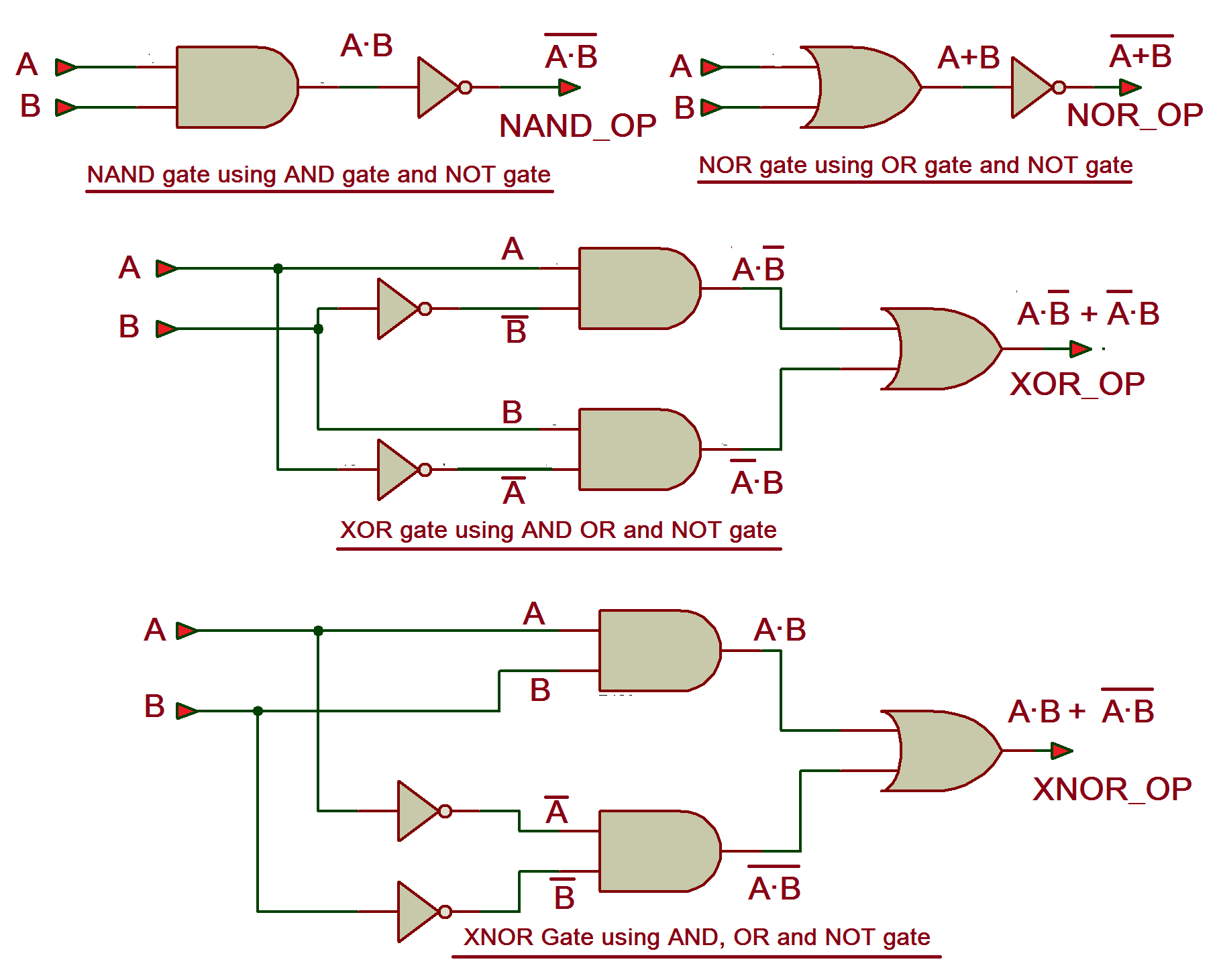
All Gate Examples And Nand Or Nor Circuit Diagram
Building the NAND
3. The NAND Gate Assembly
Alright, let's get to the exciting part: actually building the NAND gate. You'll need three NOR gates in total. Remember, we're using two of them as NOT gates, so we'll connect their inputs together as we discussed. Let's call our original inputs A and B. We need to invert both A and B before feeding them into the final NOR gate.
Connect input A to the tied-together inputs of your first NOR gate (which is now a NOT gate). This NOT gate's output will be the inverse of A (let's call it NOT A). Similarly, connect input B to the tied-together inputs of your second NOR gate (another NOT gate). This NOT gate's output will be the inverse of B (NOT B).
Now, take the outputs of those two NOT gates (NOT A and NOT B) and feed them as inputs to the third NOR gate. The output of this final NOR gate is your NAND output! Congratulations, you've successfully built a NAND gate using only NOR gates. You should be proud of yourself. It's like conducting a tiny electronic symphony.
To summarize:
Now you can impress your friends with your newfound logic gate mastery. Or, you know, just bask in the glow of your own digital accomplishment.
- Create two NOT gates by tying the inputs of two NOR gates together.
- Connect input A to the first NOT gate, creating NOT A.
- Connect input B to the second NOT gate, creating NOT B.
- Feed NOT A and NOT B as inputs to the third NOR gate.
- The output of the third NOR gate is the NAND output!

Circuit Diagram Of Xor Gate Using Nand Circui
Testing Your Creation
4. Verifying the NAND Gate's Functionality
Okay, you've built your NAND gate from NOR gates. Awesome! But how do you know it's actually working correctly? Well, the best way is to test it thoroughly. Remember, a NAND gate only outputs FALSE (0) when both inputs are TRUE (1). In all other cases, it should output TRUE (1).
Create a truth table. This is a simple table that shows all possible input combinations (A and B) and the corresponding output. Here's what your truth table should look like:
A | B | Output ---|---|------- 0 | 0 | 1 0 | 1 | 1 1 | 0 | 1 1 | 1 | 0
Systematically apply each of these input combinations to your circuit and check the output. If your circuit matches this truth table perfectly, then congratulations! You've successfully built a functional NAND gate. If not, double-check your wiring and make sure everything is connected correctly. It's easy to make a small mistake, so don't get discouraged.You can use LEDs to visually represent the inputs and output. A lit LED could represent TRUE (1), and an unlit LED could represent FALSE (0). This makes it easy to see the gate's behavior in real-time. If you have access to a logic analyzer or an oscilloscope, you can use those tools for more precise measurements and debugging.
Testing is a crucial step in any electronics project. It's the only way to be sure that your circuit is working as intended. So, don't skip this step! And remember, even if you encounter problems, that's just part of the learning process. Debugging is a valuable skill in itself, and it will make you a better electronics enthusiast in the long run. Plus, the satisfaction of finally getting your circuit to work is all the sweeter after overcoming a challenge!

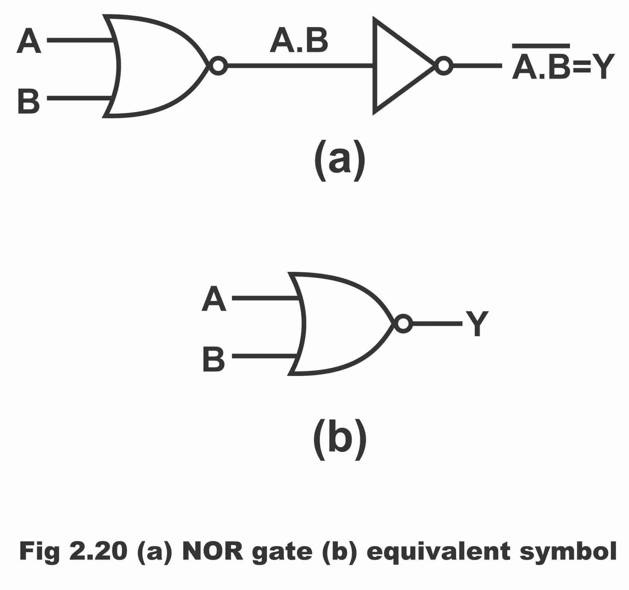
Logic NOR Gate Working Principle & Circuit Diagram
Why Bother? The Importance of Logic Gate Conversions
5. Practical Applications and Deeper Understanding
So, why go through the trouble of building a NAND gate from NOR gates? Is it just a fun little exercise, or is there a deeper significance? Well, there are several reasons why this kind of logic gate conversion is important. First, it demonstrates the universality of certain gates. Both NAND and NOR gates are considered "universal" because you can build any other logic gate (AND, OR, XOR, etc.) using only them.
This universality is incredibly useful in digital circuit design. Imagine you're designing a complex circuit, and you only have a limited number of a specific type of gate (say, NOR gates) available. Knowing that you can build any other gate you need from those NOR gates gives you a lot of flexibility and allows you to optimize your design. It's like having a secret weapon in your digital arsenal.
Furthermore, understanding these conversions gives you a deeper understanding of how logic gates work and how they can be combined to create more complex functions. It forces you to think about the fundamental principles of Boolean algebra and digital logic. It's not just about memorizing truth tables; it's about understanding the underlying relationships between different gates.
Finally, these kinds of exercises can be a great way to improve your problem-solving skills. Figuring out how to build one gate from another requires creative thinking and a bit of trial and error. It's a great way to challenge yourself and expand your knowledge of digital electronics. And who knows, maybe you'll even come up with some new and innovative circuit designs along the way! So, keep experimenting, keep learning, and keep building! The possibilities are endless.

FAQs
6. Your Questions Answered
Q: Can I build other logic gates using only NOR gates?
A: Absolutely! As we discussed, NOR gates are universal. You can create AND, OR, XOR, and any other gate you need using just NOR gates. It might require a bit of clever arrangement, but it's definitely possible. There are plenty of online resources and tutorials that can guide you through the process.
Q: Why are NAND and NOR gates so popular?
A: Their universality is a big part of it. Also, they're relatively simple to implement in hardware using transistors. This makes them cost-effective and efficient to use in digital circuits. Plus, their inverting nature can be very useful for certain circuit designs.
Q: Is it always practical to build other gates from NAND or NOR?
A: Not always. In some cases, it might be more efficient to use dedicated gates for specific functions. However, in situations where you have limited gate options or you're trying to minimize the number of different gate types, these conversions can be very valuable.